 Electro
555 Timer LED Flasher Circuit (Astable Mode) — Build and Calculate
Build a 555 timer LED flasher in astable mode. Pin-by-pin NE555 table, frequency formula f = 1.44/((R1+2R2)C) with a worked example, and fixes.
On this page
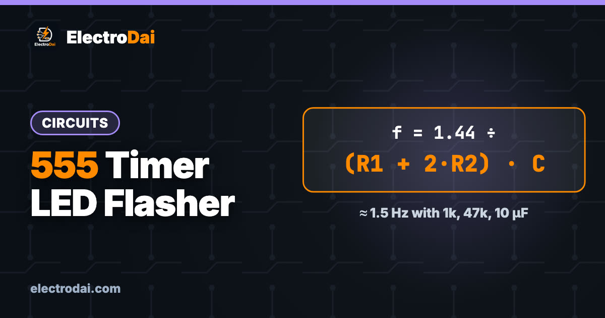
The NE555 is one of the oldest and most loved chips in electronics, and it is still sold in every electronics market in Nepal. With two resistors, one capacitor and an LED you can make it blink without any code or microcontroller. In this tutorial you will build a 555 LED flasher, learn what each of the 8 pins does, and calculate the blink speed yourself so you can choose any rate you like.
"Astable" simply means the output never settles: it keeps switching between HIGH and LOW by itself. That is exactly what you want from a flasher, a buzzer tone generator or a clock pulse.
Safety note
This circuit runs from a 9 V battery or a 5 V to 12 V DC supply. It is safe to touch, but a 9 V battery can still heat a wire or a resistor if you short it. Never build this on mains voltage, and connect the battery last.
What you need
Scroll sideways to see all columns.
| Item | Qty | Notes |
|---|---|---|
| NE555 timer IC (8-pin DIP) | 1 | Also marked LM555 or NE555P. Avoid chips with no marking |
| Resistor 1 kΩ (R1) | 1 | Brown-black-red |
| Resistor 47 kΩ (R2) | 1 | Yellow-violet-orange |
| Electrolytic capacitor 10 µF, 16 V or more (C1) | 1 | Long leg is + |
| Ceramic capacitor 100 nF, marked 104 (C2) | 1 | Optional but recommended, steadies pin 5 |
| Ceramic capacitor 100 nF (C3) | 1 | Supply bypass, close to pins 8 and 1 |
| LED 5 mm, any colour | 1 | Long leg = anode (+) |
| Resistor 470 Ω (R3, LED resistor) | 1 | Yellow-violet-brown |
| 9 V battery with snap clip | 1 | Or 5 V to 12 V DC supply |
| Breadboard and jumper wires | 1 set | Half-size is enough |
| Digital multimeter | 1 | For the test section |
NE555 pin-by-pin table
Hold the chip with the small notch (or dot) at the top. Pin 1 is at the top left, and pins count anticlockwise.
Scroll sideways to see all columns.
| Pin | Name | What it does in this circuit |
|---|---|---|
| 1 | GND | Ground (0 V) |
| 2 | TRIG | When it falls below 1/3 of supply, the output goes HIGH |
| 3 | OUT | Output; drives the LED |
| 4 | RESET | Held HIGH (connect to +V) so the chip runs. Pull to GND to stop it |
| 5 | CTRL | Control voltage. Left unused; add 100 nF to GND to reduce noise |
| 6 | THR | When it rises above 2/3 of supply, the output goes LOW |
| 7 | DISCH | Discharges the capacitor through R2 during the LOW time |
| 8 | VCC | Positive supply, 4.5 V to 16 V for NE555 |
Wiring table
Scroll sideways to see all columns.
| From | To |
|---|---|
| Battery + | Pin 8, Pin 4, one end of R1 |
| Battery − | Pin 1, − leg of C1, one end of C2 |
| R1 other end | Pin 7 and one end of R2 |
| R2 other end | Pin 6 and Pin 2 (joined together) |
| C1 + leg | Pin 2 (and Pin 6) |
| C2 other end | Pin 5 |
| C3 | Between pins 8 and 1, close to the chip |
| Pin 3 | One end of R3 (470 Ω) |
| R3 other end | LED anode (long leg) |
| LED cathode (short leg) | Battery − |
Signal path in one line:
+V → R1 → (pin 7) → R2 → (pins 6+2) → C1 → GND ; pin 3 → R3 → LED → GND
How it works (simple version)
Inside the 555 there are two comparators and a switch. They watch the voltage across the capacitor C1.
- C1 starts empty. The voltage on pin 2 is low, so the output (pin 3) is HIGH and the LED is on.
- C1 charges slowly through R1 + R2 (the high time).
- When C1 reaches 2/3 of the supply, the internal switch at pin 7 turns on and the output goes LOW. The LED is off.
- C1 now discharges through R2 only, into pin 7 (the low time).
- When C1 falls to 1/3 of the supply, the chip flips again and the cycle repeats.
Because C1 charges through R1 + R2 but discharges through R2 only, the LED is on for slightly longer than it is off.
The formulas
For the standard astable circuit:
- Frequency: f = 1.44 / ((R1 + 2 × R2) × C)
- High time: t_high = 0.693 × (R1 + R2) × C
- Low time: t_low = 0.693 × R2 × C
- Period: T = t_high + t_low = 1 / f
Use ohms for R and farads for C. 10 µF = 0.00001 F.
Worked example (the values in this build)
R1 = 1 kΩ = 1,000 Ω, R2 = 47 kΩ = 47,000 Ω, C = 10 µF = 0.00001 F.
- R1 + 2 × R2 = 1,000 + 94,000 = 95,000 Ω
- (R1 + 2 × R2) × C = 95,000 × 0.00001 = 0.95 s
- f = 1.44 / 0.95 ≈ 1.52 Hz, about 1.5 blinks per second
Check the times:
- t_high = 0.693 × 48,000 × 0.00001 ≈ 0.333 s
- t_low = 0.693 × 47,000 × 0.00001 ≈ 0.326 s
- Total = 0.659 s, and 1 / 0.659 ≈ 1.52 Hz. The two methods agree.
The duty cycle (percentage of time HIGH) is t_high / T = 0.333 / 0.659 ≈ 50.5%. Making R2 much larger than R1 keeps the duty cycle close to 50%.
Change the speed
Scroll sideways to see all columns.
| Goal | Change | New frequency (approx.) |
|---|---|---|
| Slower, about 0.7 Hz | C1 = 22 µF (R1 1 kΩ, R2 47 kΩ) | 1.44 / (95,000 × 0.000022) ≈ 0.69 Hz |
| Faster, about 15 Hz | C1 = 1 µF | 1.44 / (95,000 × 0.000001) ≈ 15.2 Hz |
Real parts are not exact: the real frequency depends on the resistor and capacitor tolerances and capacitor leakage.
Step-by-step build
- Place the NE555 across the centre gap of the breadboard, notch at the top. Check that pins 1-4 are on one side and pins 5-8 on the other.
- Connect pin 8 and pin 4 to the + rail. Connect pin 1 to the − rail.
- Put R1 between the + rail and pin 7.
- Put R2 between pin 7 and pin 6.
- Join pin 6 and pin 2 with a short jumper wire.
- Place C1 with the + leg on pin 2 and the − leg on the − rail. Reversing an electrolytic capacitor can make it hot or burst, so check the stripe.
- Place C2 (100 nF) between pin 5 and the − rail. Place C3 directly across the supply near pins 8 and 1.
- Connect pin 3 to R3, R3 to the LED anode, and the LED cathode to the − rail.
- Connect the battery. The LED should blink about 1.5 times per second.
Testing with a multimeter
Set the meter to DC volts.
- Supply check: red probe on pin 8, black on pin 1. You should see the battery voltage (about 9 V, a new battery may show 9.4 V).
- Capacitor voltage (pin 2 to GND): the reading swings between about 3 V and 6 V on a 9 V supply (1/3 and 2/3 of supply). At 1.5 Hz your meter may follow the average, around 4.5 V. At this speed, use a larger C1 such as 100 µF to see the readings climb and fall slowly.
- Output (pin 3 to GND): when the LED is on you should read roughly 7 V to 7.5 V on a 9 V supply. A bipolar NE555 does not reach the full supply voltage on its output, which is normal. When off, the reading is close to 0 V.
- Continuity (power off): pins 2 and 6 should beep together, and pin 4 should beep to the + rail.
Troubleshooting
Scroll sideways to see all columns.
| Symptom | Likely cause | Fix |
|---|---|---|
| LED stays on, never blinks | Pin 2 and pin 6 not joined, or C1 missing | Join pins 2 and 6, check C1 is in the circuit |
| LED stays off | LED reversed, or pin 4 (RESET) not connected to + | Flip the LED; connect pin 4 to + |
| Nothing at all, chip gets warm | Chip inserted backwards | Power off, turn the notch to the top |
| Blink rate far from the calculation | Wrong resistor or capacitor value (e.g. 4.7 k instead of 47 k) | Disconnect power and lift one end of each resistor before measuring |
FAQ
Can I make the LED on-time shorter than the off-time?
Not with this basic circuit, since t_high is always longer than t_low. To get a short flash, swap the LED so it lights when the output is LOW (connect the LED from +V to pin 3 through the resistor).
Can I drive a buzzer instead of the LED?
Yes. A small passive piezo sounder on pin 3 with C1 = 10 nF gives a tone of about 1.5 kHz. An active buzzer just clicks at the blink rate.

Clap Switch Circuit Using a Sound Sensor Module and Arduino
Build a double-clap switch with a sound sensor module and Arduino Uno. Wiring table, full commented code, calibration steps and fixes.

Rain Alarm Circuit Using a Rain Sensor and Buzzer (With and Without Arduino)
Build a rain alarm with a rain sensor module and buzzer, first with a BC557 transistor and then with Arduino. Wiring tables, code and fixes.

Automatic Street Light Circuit Using LDR and BC547 Transistor
Build an automatic street light that turns on in the dark with an LDR and a BC547 transistor. Wiring table, calculations, tuning and fixes.