 Electro
ESP32-CAM Getting Started: Upload, Flash LED and Motion Photo
Upload code to the ESP32-CAM with a USB-serial adapter, fix brownout and Connecting errors, use the GPIO4 flash LED, and take a PIR motion photo.
On this page
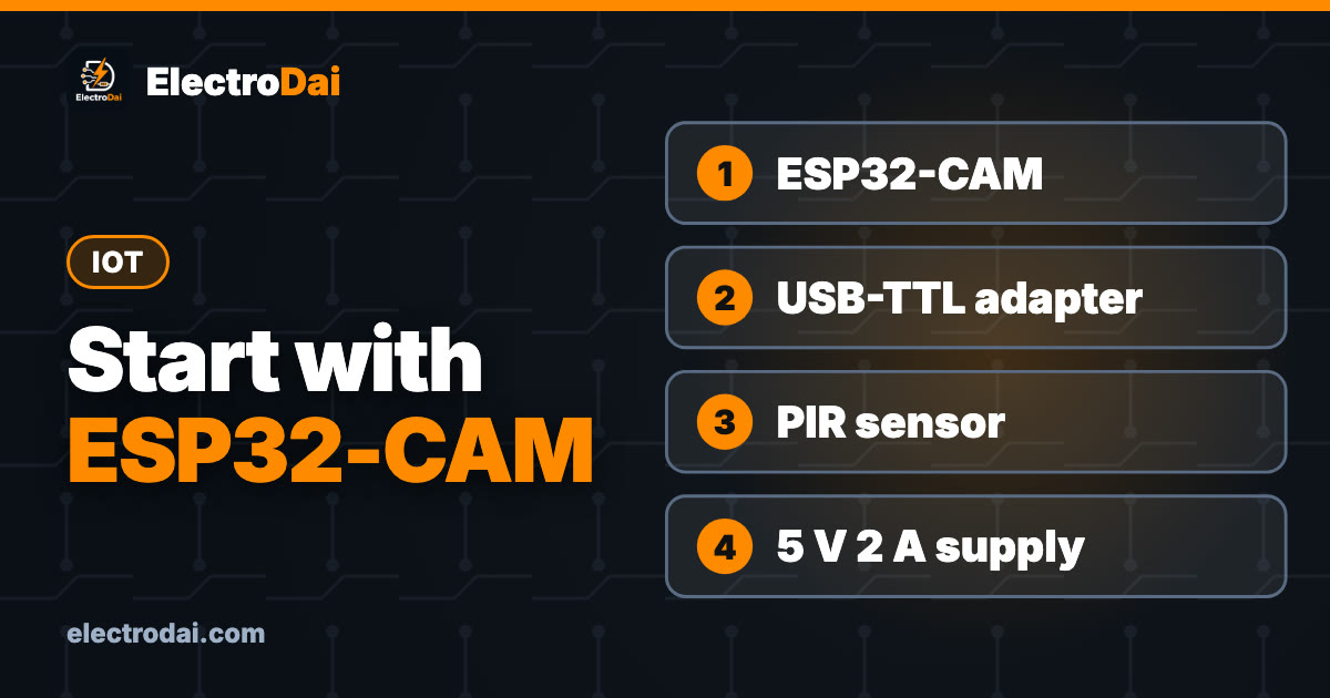
The ESP32-CAM is a tiny board with an ESP32, a camera, a microSD slot and a very bright flash LED. It can stream video to your phone, take photos on motion, and become the eye of a robot or a final-year project. It also confuses almost every beginner on day one, because it has no USB port.
This guide uses the common AI-Thinker ESP32-CAM with the OV2640 camera. You will upload code, run the camera web server, control the flash LED, and build a motion photo trap that wakes on a PIR sensor and saves a picture to the SD card.
What you need
Scroll sideways to see all columns.
| Item | Qty | Notes |
|---|---|---|
| ESP32-CAM (AI-Thinker) with OV2640 camera | 1 | Check the ribbon cable is latched |
| USB-to-serial adapter (FTDI / CP2102 / CH340) | 1 | Or the "ESP32-CAM-MB" base board |
| microSD card (formatted FAT32) | 1 | For the motion photo project |
| HC-SR501 PIR motion sensor | 1 | Output is about 3.3 V, safe for the ESP32 |
| Stable 5 V supply | 1 | Good USB adapter or power bank; see "Power" below |
| Jumper wires (female-female) | 6+ | |
| Short jumper or wire for GPIO0 | 1 | Upload mode link |
Board tour
Scroll sideways to see all columns.
| Pin or part | What it is |
|---|---|
| 5V, GND | Power input. Use 5V for a stable supply |
| U0T (GPIO1), U0R (GPIO3) | Serial TX and RX for uploading and Serial Monitor |
| GPIO0 | Boot mode pin. Tied to GND = upload mode. Also used as the camera clock |
| GPIO4 | The bright flash LED (also an SD card data line) |
| GPIO33 | Small red LED on the back, on when the pin is LOW |
| RST button | Reset, usually on the underside |
| GPIO2, 12, 13, 14, 15 | Used by the SD card; some are free when the SD card runs in 1-bit mode |
Many pins are already used by the camera, so the ESP32-CAM has far fewer free GPIOs than a normal ESP32 board.
Wiring for upload
Scroll sideways to see all columns.
| USB-serial adapter | ESP32-CAM |
|---|---|
| Regulated 5 V supply positive | 5V |
| Adapter and supply GND | GND |
| TX (3.3 V logic) | U0R (GPIO3) |
| RX (3.3 V logic) | U0T (GPIO1) |
| — | GPIO0 to GND (only while uploading) |
TX and RX are crossed: the adapter's transmit goes to the board's receive. If you use the MB base board, just plug the ESP32-CAM onto it. The MB board has its own buttons for boot mode.
Use a regulated 5 V source for the board and a 3.3 V logic adapter for UART. Check what the adapter’s voltage jumper controls before connecting TX. Leave the adapter power lead disconnected when using a separate supply.
Upload your first sketch
- In Arduino IDE 2, install the esp32 by Espressif Systems board package from Boards Manager if you have not already.
- Select Tools → Board → esp32 → AI Thinker ESP32-CAM and the adapter's port.
- Connect GPIO0 to GND, then press the RST button. The board is now in upload mode.
- Click Upload. If it stops at "Connecting...", press RST again while it waits.
- When upload finishes, remove the GPIO0 link and press RST. The sketch now runs.
Start with the camera web server: File → Examples → ESP32 → Camera → CameraWebServer. In the example, select the CAMERA_MODEL_AI_THINKER model (depending on your board package version, this line is in the main sketch or in board_config.h), enter your Wi-Fi name and password, upload, then open the Serial Monitor at 115200 baud. It prints an IP address. Open it in a browser on the same Wi-Fi and press Start Stream. If you have built our ESP32 web server LED project, the idea is the same, with images instead of a button.
Power: fix the brownout error
The most common ESP32-CAM error is:
Brownout detector was triggered
The camera and Wi-Fi together draw sudden bursts of current. When the supply voltage dips, the chip resets itself. Fixes:
- Power from the 5V pin, not the 3.3V pin, and use a supply that can comfortably give at least 1 A.
- Use short, thick wires. Thin, long jumper wires drop voltage.
- Do not rely on a weak USB-serial adapter's 3.3 V output to run the board.
- Add a 100 µF to 470 µF capacitor across 5V and GND near the board if resets continue.
Do not "fix" brownout by disabling the detector in code. It hides a real power problem that will cause random crashes later.
The flash LED (GPIO4)
The flash LED is very bright. Do not look straight into it at close range, and keep it off unless you are taking a photo. To control it in your own code, set GPIO4 as an output, or dim it with PWM using ledcAttach() and ledcWrite() (the exact LEDC function names differ between older and newer esp32 board package versions). Because GPIO4 is also an SD card data line, the flash can flicker when the SD card is used in 4-bit mode. Using the SD card in 1-bit mode avoids this.
Project: motion photo trap
The PIR sensor's output goes HIGH when it sees movement. We connect it to GPIO13 and use it to wake the ESP32 from deep sleep. The board takes one photo, saves it to the SD card, and goes back to sleep.
Scroll sideways to see all columns.
| From | To |
|---|---|
| PIR VCC | 5V |
| PIR GND | GND |
| PIR OUT | ESP32-CAM GPIO13 |
GPIO13 is free here because we use the SD card in 1-bit mode. Our PIR motion sensor guide explains how to set its sensitivity and delay knobs.
// ESP32-CAM PIR motion photo to SD card - not compiled yet
#include "esp_camera.h"
#include "FS.h"
#include "SD_MMC.h"
#include "driver/rtc_io.h"

// AI-Thinker camera pins
#define PWDN_GPIO_NUM 32
#define RESET_GPIO_NUM -1
#define XCLK_GPIO_NUM 0
#define SIOD_GPIO_NUM 26
#define SIOC_GPIO_NUM 27
#define Y9_GPIO_NUM 35
#define Y8_GPIO_NUM 34
#define Y7_GPIO_NUM 39
#define Y6_GPIO_NUM 36
#define Y5_GPIO_NUM 21
#define Y4_GPIO_NUM 19
#define Y3_GPIO_NUM 18
#define Y2_GPIO_NUM 5
#define VSYNC_GPIO_NUM 25
#define HREF_GPIO_NUM 23
#define PCLK_GPIO_NUM 22

RTC_DATA_ATTR int photoCount = 0;   // survives deep sleep

bool startCamera() {
  camera_config_t c = {};
  c.ledc_channel = LEDC_CHANNEL_0;
  c.ledc_timer = LEDC_TIMER_0;
  c.pin_d0 = Y2_GPIO_NUM; c.pin_d1 = Y3_GPIO_NUM;
  c.pin_d2 = Y4_GPIO_NUM; c.pin_d3 = Y5_GPIO_NUM;
  c.pin_d4 = Y6_GPIO_NUM; c.pin_d5 = Y7_GPIO_NUM;
  c.pin_d6 = Y8_GPIO_NUM; c.pin_d7 = Y9_GPIO_NUM;
  c.pin_xclk = XCLK_GPIO_NUM; c.pin_pclk = PCLK_GPIO_NUM;
  c.pin_vsync = VSYNC_GPIO_NUM; c.pin_href = HREF_GPIO_NUM;
  c.pin_sccb_sda = SIOD_GPIO_NUM; c.pin_sccb_scl = SIOC_GPIO_NUM;
  c.pin_pwdn = PWDN_GPIO_NUM; c.pin_reset = RESET_GPIO_NUM;
  c.xclk_freq_hz = 20000000;
  c.pixel_format = PIXFORMAT_JPEG;
  c.frame_size = FRAMESIZE_SVGA;     // 800x600
  c.jpeg_quality = 12;               // lower number = better quality
  c.fb_count = 1;
  return esp_camera_init(&c) == ESP_OK;
}

void setup() {
  Serial.begin(115200);
  rtc_gpio_hold_dis(GPIO_NUM_4);     // release the flash pin after sleep

  if (!startCamera()) { Serial.println("Camera init failed"); }
  else if (!SD_MMC.begin("/sdcard", true)) { Serial.println("SD failed"); } // true = 1-bit mode
  else {
    delay(500);                      // let auto exposure settle
    camera_fb_t *fb = esp_camera_fb_get();
    if (fb) {
      photoCount++;
      String path = "/motion" + String(photoCount) + ".jpg";
      File f = SD_MMC.open(path, FILE_WRITE);
      if (f) { f.write(fb->buf, fb->len); f.close(); Serial.println("Saved " + path); }
      esp_camera_fb_return(fb);
    }
  }

  // keep the flash LED off during sleep
  pinMode(4, OUTPUT);
  digitalWrite(4, LOW);
  rtc_gpio_hold_en(GPIO_NUM_4);

  pinMode(13, INPUT);
  while (digitalRead(13) == HIGH) delay(50); // rearm only after the PIR returns LOW
  esp_sleep_enable_ext0_wakeup(GPIO_NUM_13, 1);  // wake when PIR goes HIGH
  Serial.println("Sleeping");
  esp_deep_sleep_start();
}

void loop() {}
The photo counter lives in RTC memory, so it survives sleep but restarts at 1 after a full power cut and could overwrite old files. For a longer project, save the counter on the SD card or name files by time.
Privacy first
A camera can record people who never agreed to it. Point it only at your own property or your own project bench, tell people in the area that a camera is there, and keep the photos secure. Do not upload pictures of people without their permission. In your project report, write a short section about privacy; examiners appreciate it.
Troubleshooting
Scroll sideways to see all columns.
| Symptom | Likely cause | Fix |
|---|---|---|
| Stuck at "Connecting..." | Not in upload mode | GPIO0 to GND, press RST, then upload |
| "No serial data received" | TX/RX not crossed, wrong port | Swap TX and RX; pick the right port |
| Uploads but nothing runs | GPIO0 still on GND | Remove the link and press RST |
| "Brownout detector was triggered" | Weak power or thin wires | Solid 5 V supply on the 5V pin, short wires |
| "Camera init failed" | Ribbon cable loose or wrong model selected | Reseat the cable; select AI Thinker |
| SD card fails | Card not FAT32, or too large for the reader | Format FAT32; try a smaller card |
| Flash LED glows during sleep | GPIO4 floating | Use the rtc_gpio_hold_en lines in the code |
FAQ
Can I upload using another ESP32 or an Arduino Uno?
Some people do, but a cheap USB-serial adapter or the MB base board is far simpler and more reliable.
Why is the stream slow?
Higher resolution and weak Wi-Fi reduce frame rate. Lower the frame size in the web page settings and keep the board close to the router.
Can it recognise faces or objects?
Simple detection is possible, but it is slow on this small chip. For vision projects consider TinyML tools or a Raspberry Pi. See our ESP32 IoT project ideas for more directions.
Can I send the photo to my phone instead of an SD card?
Yes, by connecting to Wi-Fi after waking and uploading the image to a server or messaging bot. This uses more power, so the battery will last less time.

TinyML on ESP32 with Edge Impulse: Your First On-Device Model
Train a gesture recognition model with Edge Impulse and run it on an ESP32 with an MPU6050. Data collection, training, int8 deployment and testing.

Landslide Tilt Warning Prototype with MPU6050 and LoRa (Learning Build)
Build a learning prototype that detects tilt with an MPU6050 on an ESP32 and sends alerts over LoRa to a gateway. Wiring, code, testing and limits.

Water Tank Level Monitor with ESP32 and Ultrasonic Sensor (Leak Alert)
Build a rooftop water tank level monitor with ESP32 and a JSN-SR04T or HC-SR04: level % formula, median filter, phone page, night leak alert and mois…