 Electro
ESP32 IoT Dashboard with Blynk: Send Sensor Data to Your Phone
Send DHT11 temperature and humidity from an ESP32 to a Blynk dashboard on your phone. Wiring, 3.3V notes, template setup, code and fixes.
On this page
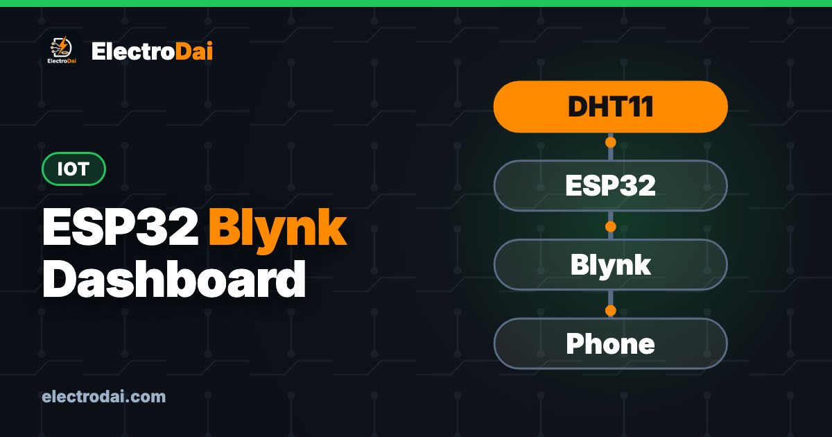
With an ESP32 and a cloud dashboard you can watch your sensor from anywhere with internet, not only on your home Wi-Fi. Blynk is a popular beginner platform for this. In this tutorial an ESP32 reads a DHT11 temperature and humidity sensor and sends the values to a Blynk dashboard on your phone. The ESP32 also lets you switch an LED from the phone.
A note about Blynk: the Blynk IoT platform changes from time to time (menus, names, free plan limits). The steps below describe the general idea of the current Blynk IoT platform (Blynk.Cloud and the Blynk mobile app). Steps may change, so check the official Blynk docs if a screen looks different from what is written here.
Safety note
This project uses 3.3 V logic and USB power only. Never put your Wi-Fi password or your Blynk authentication token in a screenshot, a video or a public code repository.
What you need
Scroll sideways to see all columns.
| Item | Qty | Notes |
|---|---|---|
| Classic ESP32 DevKit board + data USB cable | 1 | |
| DHT11 sensor module (3-pin) | 1 | Choose a module rated for 3.3 V with a built-in pull-up. A bare 4-pin sensor needs a 10 kΩ pull-up from VCC to DATA |
| LED 5 mm | 1 | Optional, for control from the phone |
| Resistor 220 Ω | 1 | For the LED |
| Breadboard and jumper wires | 1 set | |
| 2.4 GHz Wi-Fi with internet | 1 | |
| Free Blynk account and the Blynk app on your phone | 1 | |
| Digital multimeter | 1 |
How it works
Blynk has three parts: the cloud (Blynk.Cloud), your device (the ESP32 running the Blynk library) and your dashboard (web and phone app). The ESP32 connects to your Wi-Fi, then to the cloud using a secret authentication token.
Data travels through datastreams. A datastream is a named channel, such as "Temperature", linked to a virtual pin like V0. The sketch writes a value to V0 with Blynk.virtualWrite, and a gauge widget on the dashboard displays it. For control, a switch widget writes to a virtual pin such as V2, and the sketch reacts in a function that runs when V2 changes.
Reminder about the ESP32: its GPIO pins are 3.3 V logic and not 5 V tolerant. Use a DHT11 module rated for 3.3 V and power it from 3V3, which keeps the pull-up at a safe level. GPIO 4 is used as a digital pin here, so the ADC2 restriction during Wi-Fi does not apply.
Connection table
Scroll sideways to see all columns.
| Component pin | ESP32 pin |
|---|---|
| DHT11 VCC (+) | 3V3 |
| DHT11 DATA (OUT) | GPIO 4 |
| DHT11 GND (−) | GND |
| 10 kΩ pull-up (bare sensor only) | Between DHT11 VCC and DATA |
| LED anode via 220 Ω | GPIO 23 |
| LED cathode | GND |
Signal path in one line:
DHT11 → GPIO 4 → ESP32 → Wi-Fi → Blynk.Cloud → phone gauge; phone switch → cloud → ESP32 → GPIO 23 → LED
Step-by-step build
- Wire the DHT11 and LED to the ESP32 as in the table.
- Install libraries in Arduino IDE 2 Library Manager: Blynk (IoT library 1.x by Volodymyr Shymanskyy), DHT sensor library (Adafruit) and Adafruit Unified Sensor. Make sure the esp32 board package is installed (see our ESP32 web server tutorial).
- Create a Blynk account and sign in to Blynk.Console in your browser.
- Create a template: go to Developer Zone → My Templates → New Template. Give it a name, select ESP32 hardware and choose Wi-Fi.
- Open the template’s Datastreams tab and add three Virtual Pin datastreams: V0 "Temperature" (double, 0 to 50), V1 "Humidity" (double, 0 to 100) and V2 "LED" (integer, 0 to 1).
- Open the template’s Web Dashboard, add gauges linked to V0 and V1 and a switch linked to V2, then save the template. Configure the same widgets separately in the Blynk mobile app if you want native app controls.
- Go to Devices → New Device, select your template and create the device. Copy Template ID and Template Name from the template firmware configuration, and the device’s Auth Token from Device Info.
- Enter your Wi-Fi name and password, upload the sketch, and wait for the device to turn online in Blynk.
The code
// ElectroDai - ESP32 + DHT11 + Blynk IoT
// Replace the placeholders with YOUR values from Blynk. Keep them private.

#define BLYNK_TEMPLATE_ID   "YOUR_TEMPLATE_ID"
#define BLYNK_TEMPLATE_NAME "YOUR_TEMPLATE_NAME"
#define BLYNK_AUTH_TOKEN    "YOUR_AUTH_TOKEN"
#define BLYNK_PRINT Serial

#include <WiFi.h>
#include <BlynkSimpleEsp32.h>
#include "DHT.h"

char ssid[] = "YOUR_WIFI_NAME";
char pass[] = "YOUR_WIFI_PASSWORD";

#define DHTPIN 4
#define DHTTYPE DHT11
const int LED_PIN = 23;

DHT dht(DHTPIN, DHTTYPE);
BlynkTimer timer;

// Runs every few seconds: read the sensor and send the values
void sendSensorData() {
  float h = dht.readHumidity();
  float t = dht.readTemperature();
  if (isnan(h) || isnan(t)) {
    Serial.println("DHT read failed");
    return;                          // skip this round
  }
  if (!Blynk.connected()) return;
  Blynk.virtualWrite(V0, t);         // Temperature datastream
  Blynk.virtualWrite(V1, h);         // Humidity datastream
  Serial.printf("Temp %.1f C, Humidity %.0f %%\n", t, h);
}

// Runs when the switch on V2 changes in the app
BLYNK_WRITE(V2) {
  int value = param.asInt();         // 1 = ON, 0 = OFF
  digitalWrite(LED_PIN, value ? HIGH : LOW);
}

void setup() {
  Serial.begin(115200);
  pinMode(LED_PIN, OUTPUT);
  digitalWrite(LED_PIN, LOW);
  dht.begin();
  Blynk.begin(BLYNK_AUTH_TOKEN, ssid, pass);   // connect to Wi-Fi and Blynk
  timer.setInterval(5000L, sendSensorData);    // every 5 seconds
}

void loop() {
  Blynk.run();
  timer.run();
}
The sketch sends data every 5 seconds. The DHT11 allows about one reading per second at most, and free cloud plans have message limits, so do not send faster than you need.
Testing with a multimeter
- 3V3 rail: about 3.3 V between 3V3 and GND.
- DHT11 supply: the same 3.3 V between sensor VCC and GND.
- Data line idle: DATA to GND should rest near 3.3 V because of the pull-up.
- LED control: tap the switch in the app. GPIO 23 to GND should read about 3.3 V when ON and 0 V when OFF.
- Reality check: breathe on the sensor and watch the humidity gauge rise on your phone.
Troubleshooting
Scroll sideways to see all columns.
| Symptom | Likely cause | Fix |
|---|---|---|
| Compile error about template ID | #define lines placed after the includes |
Move them to the very top |
| Device stays offline | Wrong token, Wi-Fi name or password, or no internet | Re-copy the values; use 2.4 GHz Wi-Fi |
| Gauges show no data | Datastream and virtual pin mismatch | Match V0 and V1 in the template and the code |
| "DHT read failed" | Wrong pin or loose wire | Check GPIO 4, power and the pull-up |
| Upload stuck at "Connecting" | Board not in download mode | Hold BOOT while uploading |
| Switch does nothing | V2 not linked to the switch widget | Set the widget datastream to V2 |
| Disconnects often | Weak Wi-Fi or power | Move closer to the router; use a stable USB supply |
| Token exposed publicly | Shared screenshot or code | Regenerate the token in Blynk and update the sketch |
FAQ
Is Blynk free?
Blynk has offered a free plan with limits, and plans change. Check the current pricing and limits on the Blynk website before building something larger.
Can I use an Arduino Uno instead?
An Uno has no Wi-Fi. Use an ESP32 or ESP8266, or add a Wi-Fi shield or module.
What are virtual pins?
They are software channels, not physical pins. They carry values between your sketch and the dashboard.
Is the connection secure?
The token acts like a password. Keep it private. For serious products, read the platform's security guidance.
Next step: see more ideas in ESP32 IoT Project Ideas for Students.

TinyML on ESP32 with Edge Impulse: Your First On-Device Model
Train a gesture recognition model with Edge Impulse and run it on an ESP32 with an MPU6050. Data collection, training, int8 deployment and testing.

ESP32-CAM Getting Started: Upload, Flash LED and Motion Photo
Upload code to the ESP32-CAM with a USB-serial adapter, fix brownout and Connecting errors, use the GPIO4 flash LED, and take a PIR motion photo.

Landslide Tilt Warning Prototype with MPU6050 and LoRa (Learning Build)
Build a learning prototype that detects tilt with an MPU6050 on an ESP32 and sends alerts over LoRa to a gateway. Wiring, code, testing and limits.