 Electro
Battery Voltage Monitor with Arduino (Voltage Divider, Low Voltage Only)
Measure a 12 V or 7.4 V battery with Arduino A0 using a voltage divider. Formula, wiring table, calibration, low-battery alarm code and fixes.
On this page
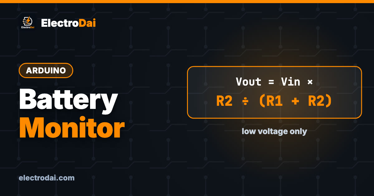
Robots slow down, sensor nodes go silent and solar projects stop overnight, and usually the reason is a battery nobody was watching. An Arduino can watch it for you. With two resistors you can read a 12 V lead-acid battery or a 2-cell Li-ion pack on an analog pin, show the voltage, and sound a warning before the battery runs too low.
This guide is for low-voltage DC batteries only, up to about 24 V. Never connect a voltage divider or an Arduino pin to mains (230 V AC) wiring. Anything involving house wiring is a job for a qualified electrician.
What you need
Scroll sideways to see all columns.
| Item | Qty | Notes |
|---|---|---|
| Arduino Uno or Nano | 1 | 5 V board, 10-bit ADC |
| Resistor 39 kΩ (R1) | 1 | 1 % metal film if you have it |
| Resistor 10 kΩ (R2) | 1 | 1 % metal film if you have it |
| Capacitor 0.1 µF (ceramic) | 1 | Smooths the reading |
| Buzzer (active, 5 V) | 1 | Low-battery alarm |
| LED + 220 Ω resistor | 1 | Visual warning |
| Battery to measure | 1 | 12 V lead-acid, 2S Li-ion (7.4 V), or similar |
| Inline fuse holder and small fuse | 1 | On the battery positive wire |
| Digital multimeter | 1 | For calibration |
| Breadboard, jumper wires | 1 set |
Why you need a divider
An Uno analog pin accepts 0 V to 5 V. A 12 V battery connected directly would damage the pin and probably the whole chip. A voltage divider is two resistors in series across the battery. The middle point gives a smaller voltage that is always the same fraction of the battery voltage.
V_pin = V_bat × R2 ÷ (R1 + R2)
Turned around to find the battery voltage:
V_bat = V_pin × (R1 + R2) ÷ R2
With R1 = 39 kΩ and R2 = 10 kΩ, the ratio is 49 ÷ 10 = 4.9. So:
Scroll sideways to see all columns.
| Battery voltage | Voltage at A0 |
|---|---|
| 7.4 V | 1.51 V |
| 12.6 V | 2.57 V |
| 14.4 V (charging) | 2.94 V |
| 24.5 V | 5.00 V (the maximum) |
That range covers a 12 V battery even while it charges, with plenty of margin. The resolution is about 24.5 V ÷ 1023 ≈ 24 mV per step, which is fine for a battery monitor. If you only measure a 2S pack (up to 8.4 V), you could use R1 = 10 kΩ and R2 = 10 kΩ for better resolution, as long as the top value stays under 10 V. Our Ohm's law guide walks through divider maths step by step.
The divider draws a small current all the time: 12.6 V ÷ 49 kΩ ≈ 0.26 mA. That is negligible for a car-size battery but worth knowing for a small pack left for weeks.
Connection table
Scroll sideways to see all columns.
| From | To |
|---|---|
| Battery + | Fuse, then one end of R1 (39 kΩ) |
| R1 other end | Arduino A0 and one end of R2 (10 kΩ) |
| R2 other end | Arduino GND |
| 0.1 µF capacitor | Between A0 and GND, close to the Arduino |
| Battery − | Arduino GND |
| Buzzer + | Arduino D8 |
| Buzzer − | GND |
| LED (through 220 Ω) | Arduino D7 → resistor → LED long leg; LED short leg → GND |
The battery negative must connect to Arduino GND, otherwise the reading has no reference. If the Arduino is powered from the same battery through a regulator, that ground is already shared.
Calibrate with a multimeter
Two things make the raw reading inaccurate: the real resistor values (a 5 % resistor can be off by 5 %) and the real 5 V reference, which on USB power is often 4.8 V to 5.1 V rather than exactly 5.0 V.
- Measure R1 and R2 with the multimeter before you fit them. Write the exact values into the code.
- Power the Arduino the way it will run in the project. Measure between the 5V pin and GND. Write that into
VREF. - Measure the battery voltage with the meter, then compare with the Serial Monitor. If they still differ by a little, adjust
CALuntil they match.
If you have never used a meter for resistance, see our guide on testing components with a multimeter.
Complete code
// Battery voltage monitor with low-battery alarm - not compiled yet
const int BAT_PIN    = A0;
const int BUZZER_PIN = 8;
const int LED_PIN    = 7;

const float R1   = 39000.0;  // measured value of top resistor (ohms)
const float R2   = 10000.0;  // measured value of bottom resistor (ohms)
const float VREF = 5.00;     // measured voltage on the 5V pin
const float CAL  = 1.000;    // fine trim after comparing with a multimeter

// Example thresholds for a 12 V lead-acid battery. Change for your battery.
const float LOW_V    = 11.8;  // warning on below this
const float RESET_V  = 12.1;  // warning off above this (hysteresis)

bool lowWarning = false;

float readBattery() {
  long total = 0;
  for (int i = 0; i < 32; i++) {      // average 32 readings to reduce noise
    total += analogRead(BAT_PIN);
    delay(2);
  }
  float raw  = total / 32.0;
  float vPin = raw * VREF / 1023.0;
  return vPin * (R1 + R2) / R2 * CAL;
}

void setup() {
  Serial.begin(9600);
  pinMode(BUZZER_PIN, OUTPUT);
  pinMode(LED_PIN, OUTPUT);
}

void loop() {
  float vBat = readBattery();

  if (!lowWarning && vBat < LOW_V)   lowWarning = true;
  if (lowWarning && vBat > RESET_V)  lowWarning = false;

  digitalWrite(LED_PIN, lowWarning);
  if (lowWarning) {                   // short beep every loop when low
    digitalWrite(BUZZER_PIN, HIGH);
    delay(100);
    digitalWrite(BUZZER_PIN, LOW);
  }

  Serial.print("Battery: ");
  Serial.print(vBat, 2);
  Serial.println(lowWarning ? " V  LOW!" : " V");
  delay(2000);
}
The hysteresis (warning on at 11.8 V, off only above 12.1 V) stops the buzzer from chattering when the voltage hovers around one value, which happens a lot when a motor starts and stops.
Choosing thresholds
Battery voltage under load is lower than at rest, so a robot's battery may dip below the threshold every time the motors start. Read at rest when you can, or average over a few seconds.
The numbers below are common rough guides, not exact rules. Real values depend on the battery, its age, temperature and load. Check your battery's datasheet.
Scroll sideways to see all columns.
| Battery | Full (approx.) | Consider "low" around | Notes |
|---|---|---|---|
| 12 V sealed lead-acid | about 12.7 V at rest | about 11.8 V to 12.0 V | Deep discharge shortens its life |
| 2S Li-ion (7.4 V nominal) | 8.4 V | about 6.6 V to 7.0 V | Never go below the cell datasheet's minimum |
| 1S Li-ion (3.7 V nominal) | 4.2 V | about 3.3 V to 3.5 V | Use R1 = R2 = 10 kΩ |
For lithium packs, the warning is a convenience. The real protection should still come from a protection circuit (BMS) in the pack.
Upgrades
- Show it on an LCD. Add a 16x2 I2C LCD, the same one used in our distance meter build, and display voltage and a battery bar.
- Percentage display. Map voltage to an approximate percent between your "low" and "full" values, and label it clearly as an estimate.
- ESP32 version. The ESP32 ADC works at 3.3 V, is noticeably non-linear near the ends of its range, and ADC2 pins cannot be used while Wi-Fi is on. Use an ADC1 pin (for example GPIO34), pick a divider that keeps the pin under about 3 V, and calibrate against a meter.
- Log to the cloud. Send the voltage to a dashboard and get a phone alert before a remote node dies.
Troubleshooting
Scroll sideways to see all columns.
| Symptom | Likely cause | Fix |
|---|---|---|
| Reading always about 0 V | Battery − not connected to Arduino GND | Join the grounds |
| Reading jumps by 0.2 V or more | Noise, long wires, motor load | Add the 0.1 µF capacitor, average more samples |
| Reading a little different from the meter | VREF or resistor values not exact | Measure them and update the code, then trim CAL |
| Reading changes when you plug in USB | 5 V reference changed with the power source | Calibrate on the final power source |
| Buzzer chatters on and off | Thresholds too close | Widen the gap between LOW_V and RESET_V |
| Arduino pin or board damaged | Divider wired the wrong way round | R2 (small) must go to GND, R1 (big) to battery + |
FAQ
Can I measure a 24 V battery?
With these values 24.5 V is the absolute top, which leaves no margin. For 24 V systems use a larger R1, for example 68 kΩ with R2 = 10 kΩ, and recalculate.
Can I measure mains voltage this way?
No. Never connect a divider or an Arduino to mains. It is dangerous and needs isolated, certified equipment and a qualified electrician.
Why not use the ready-made "0–25 V voltage sensor" module?
You can. Most of those modules are simply a resistor divider on a small board. Building it yourself shows you exactly what is inside.
Does the divider drain my battery?
Yes, very slightly, about a quarter of a milliamp at 12 V with these values. For a battery left unused for months, add a switch or use higher resistor values with a capacitor.

MPU6050 Accelerometer and Gyro with Arduino: Tilt Angle
Wire an MPU6050 (GY-521) to Arduino over I2C, read raw accelerometer and gyro data, calculate tilt angle with atan2 and smooth it with a complementar…

Arduino Relay Module Guide: Switch Loads Safely
Learn to use a 5V relay module with Arduino to switch a 12V DC lamp or fan. Pinout, COM/NO/NC, active-LOW logic, code and safety rules.

MQ-2 Gas Leak Alarm with Arduino and Buzzer
Build a learning gas and smoke alarm with the MQ-2 sensor, Arduino Uno and buzzer. Wiring, warm-up, calibration, code and safety notes.