 Electro
MPU6050 Accelerometer and Gyro with Arduino: Tilt Angle
Wire an MPU6050 (GY-521) to Arduino over I2C, read raw accelerometer and gyro data, calculate tilt angle with atan2 and smooth it with a complementary filter.
On this page
The MPU6050 is a tiny sensor that knows which way is down and how fast it is turning. It combines a 3-axis accelerometer and a 3-axis gyroscope on one chip and talks to the Arduino over just two signal wires. Self-balancing robots, gesture controllers, tilt alarms and drone flight boards all start with a sensor like this.
In this guide you will wire the common GY-521 module to an Arduino Uno, check it with an I2C scanner, read raw values, turn them into a tilt angle in degrees, and combine accelerometer and gyro readings with a complementary filter for a smooth, stable angle.
What you need
Scroll sideways to see all columns.
| Item | Qty | Notes |
|---|---|---|
| Arduino Uno or Nano | 1 | |
| MPU6050 module (GY-521) | 1 | Has a regulator and pull-up resistors on board |
| Breadboard, jumper wires | 1 set | Short wires work best for I2C |
| Bidirectional I²C level shifter | 1 | 5 V Uno side, 3.3 V sensor side |
| Soldering iron | 1 | Most modules come with loose header pins |
| Small piece of cardboard or wood | 1 | To tilt the sensor at known angles |
Connection table
Scroll sideways to see all columns.
| GY-521 pin | Arduino Uno pin |
|---|---|
| VCC | 5V (most GY-521 boards have a 3.3 V regulator; check yours) |
| GND | GND |
| SDA | A4 via an open-drain bidirectional I²C level shifter |
| SCL | A5 via the same level shifter |
| AD0 | Leave unconnected or GND → address 0x68; to 3.3 V → 0x69 |
| INT | Not used here |
The MPU6050 chip itself runs at 3.3 V. The GY-521 module's regulator lets you feed 5 V on VCC, on modules rated for a 5 V supply. That rating covers the power input only. Connect the shifter HV reference to Uno 5 V, LV to 3.3 V and share ground. Use pull-ups on each side to its own voltage, including any already on the module or shifter. If you use a bare chip or a different module, read its datasheet first. On an Arduino Nano the I2C pins are also A4 (SDA) and A5 (SCL). On an ESP32 the usual pins are GPIO21 (SDA) and GPIO22 (SCL).
If you have used the I2C LCD in our distance meter build or DHT11 weather station, it is the same bus. Several I2C devices can share A4 and A5 as long as their addresses are different.
Step 1: Check it with an I2C scanner
// I2C scanner - not compiled yet
#include <Wire.h>

void setup() {
  Serial.begin(9600);
  Wire.begin();
  for (byte addr = 1; addr < 127; addr++) {
    Wire.beginTransmission(addr);
    if (Wire.endTransmission() == 0) {
      Serial.print("Found device at 0x");
      Serial.println(addr, HEX);
    }
  }
  Serial.println("Scan done");
}

void loop() {}
You should see 0x68. If nothing appears, check the solder joints on the header pins and the SDA/SCL wires before anything else.
How the two sensors work
Accelerometer. It measures acceleration along X, Y and Z, including gravity. When the board lies flat and still, Z reads about 1 g and X and Y read about 0. Tilt it, and gravity is shared between the axes. That lets us calculate the angle. At the default ±2 g range, 1 g reads about 16384 in raw units.
Gyroscope. It measures how fast the board is rotating, in degrees per second, around each axis. At the default ±250 °/s range, 1 °/s reads about 131 in raw units. The gyro does not know the angle directly. You must add up (integrate) rotation speed over time.
Scroll sideways to see all columns.
| Accelerometer | Gyroscope | |
|---|---|---|
| Measures | Gravity + movement | Rotation speed |
| Good at | Long-term "which way is down" | Fast, smooth changes |
| Weak at | Noisy; confused by vibration and movement | Drifts slowly over time |
Each one fixes the other's weakness, which is why we combine them.
Step 2: Tilt angle from the accelerometer
For one axis, the simple formula is:
angle = atan2(ax, az)
atan2 takes two values and returns the angle between them, handling all four quadrants. To use all three axes, the usual pitch and roll formulas are:
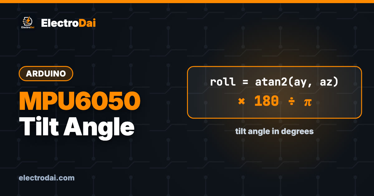
- roll = atan2(ay, az)
- pitch = atan2(−ax, √(ay² + az²))
Both return radians. Multiply by 180 ÷ π to get degrees. Which name, pitch or roll, matches which way you tilt depends on how the module is mounted, so check by tilting it.
Step 3: Add the gyro with a complementary filter
The complementary filter trusts the gyro for quick changes and the accelerometer for the long-term value:
angle = 0.98 × (angle + gyroRate × dt) + 0.02 × accelAngle
dt is the time since the last reading in seconds. The 0.98 and 0.02 weights are a common starting point; change them and see what happens. Before using the gyro, measure its offset: the small non-zero reading it gives while perfectly still. Subtracting that offset greatly reduces drift.
Complete code
// MPU6050 tilt angle with complementary filter - not compiled yet
#include <Wire.h>

const int MPU = 0x68;
float gyroOffsetX = 0, gyroOffsetY = 0;
float roll = 0, pitch = 0;
unsigned long lastMicros;

void readRaw(int16_t &ax, int16_t &ay, int16_t &az, int16_t &gx, int16_t &gy, int16_t &gz) {
  Wire.beginTransmission(MPU);
  Wire.write(0x3B);                    // ACCEL_XOUT_H, start of the data block
  Wire.endTransmission(false);
  Wire.requestFrom(MPU, 14, true);     // accel (6), temperature (2), gyro (6)
  ax = Wire.read() << 8 | Wire.read();
  ay = Wire.read() << 8 | Wire.read();
  az = Wire.read() << 8 | Wire.read();
  Wire.read(); Wire.read();            // skip temperature
  gx = Wire.read() << 8 | Wire.read();
  gy = Wire.read() << 8 | Wire.read();
  gz = Wire.read() << 8 | Wire.read();
}

void setup() {
  Serial.begin(115200);
  Wire.begin();
  Wire.beginTransmission(MPU);
  Wire.write(0x6B);                    // PWR_MGMT_1
  Wire.write(0);                       // wake up (it starts in sleep mode)
  Wire.endTransmission(true);

  // gyro offset: keep the sensor still during this
  Serial.println("Calibrating, keep still...");
  int16_t ax, ay, az, gx, gy, gz;
  for (int i = 0; i < 500; i++) {
    readRaw(ax, ay, az, gx, gy, gz);
    gyroOffsetX += gx;
    gyroOffsetY += gy;
    delay(3);
  }
  gyroOffsetX /= 500.0;
  gyroOffsetY /= 500.0;

  // start the filter at the accelerometer angle
  readRaw(ax, ay, az, gx, gy, gz);
  roll  = atan2((float)ay, (float)az) * 180.0 / PI;
  pitch = atan2(-(float)ax, sqrt((float)ay * ay + (float)az * az)) * 180.0 / PI;
  lastMicros = micros();
}

void loop() {
  int16_t ax, ay, az, gx, gy, gz;
  readRaw(ax, ay, az, gx, gy, gz);

  unsigned long now = micros();
  float dt = (now - lastMicros) / 1000000.0;
  lastMicros = now;

  float accRoll  = atan2((float)ay, (float)az) * 180.0 / PI;
  float accPitch = atan2(-(float)ax, sqrt((float)ay * ay + (float)az * az)) * 180.0 / PI;

  float rateX = (gx - gyroOffsetX) / 131.0;   // deg/s around X
  float rateY = (gy - gyroOffsetY) / 131.0;   // deg/s around Y

  roll  = 0.98 * (roll  + rateX * dt) + 0.02 * accRoll;
  pitch = 0.98 * (pitch + rateY * dt) + 0.02 * accPitch;

  Serial.print("roll:");   Serial.print(roll, 1);
  Serial.print(" pitch:"); Serial.println(pitch, 1);
  delay(10);
}
Open Tools → Serial Plotter at 115200 baud to see both angles as live graphs. Shake the board gently: the filtered angle stays calm while a raw accelerometer angle would jump.
If pitch moves the wrong way when you tilt, the gyro axis sign may not match your accelerometer formula for your mounting. Flip the sign of rateY (or rateX) and test again.
Testing your angles
- Lay the module flat. Roll and pitch should both be near 0°.
- Tilt it against a book or a protractor at about 30° and 45°. Compare with the Serial Monitor.
- Stand the board on its edge. One angle should be close to 90°.
- Leave it still for a few minutes. A gyro-only angle would drift; the filtered angle should stay steady.
Small differences of a degree or two are normal for a hobby module. For better accuracy, calibrate the accelerometer offsets too, or use a library with the chip's built-in motion processor.
Ideas to build next
- Tilt alarm. Sound a buzzer when the angle stays above a limit for several seconds. This is the core of our landslide tilt learning prototype.
- Self-balancing robot. Feed the pitch angle into a PID loop that drives two motors.
- Gesture input. Record accelerometer data for circles and waves and train a small TinyML model to recognise them.
- Digital spirit level. Show the angle on an I2C LCD.
For your first sketch with any Arduino, start with our Blink guide to make sure the board and port work.
Troubleshooting
Scroll sideways to see all columns.
| Symptom | Likely cause | Fix |
|---|---|---|
| Scanner finds nothing | Header pins not soldered, SDA/SCL swapped | Solder properly; SDA to A4, SCL to A5 |
| Found at 0x69, not 0x68 | AD0 pulled HIGH | Connect AD0 to GND or change MPU to 0x69 |
| All values read 0 | Sensor still asleep | Write 0 to register 0x6B in setup() |
| Values stuck at -1 or freeze | Loose wire, I2C bus hung | Shorten wires; press reset; check GND |
| Angle drifts slowly | Gyro offset not removed | Keep it still during calibration |
| Angle jumps with vibration | Too much weight on the accelerometer | Raise the gyro weight to 0.98 or 0.99 |
| Angle wrong near 90° | Pitch formula limits | Normal for this simple method; avoid that range or use a library with quaternions |
FAQ
Is my module a real MPU6050?
Many modules sold today use compatible or clone chips. Reading the WHO_AM_I register (0x75) should return 0x68 on a genuine MPU6050; some compatible chips return a different value but still work with this code.
Can I get yaw (compass heading)?
Not reliably. Without a magnetometer, yaw comes only from the gyro and slowly drifts. Use a 9-axis sensor if you need heading.
Why use the raw registers instead of a library?
It shows exactly what the sensor sends, which helps in a viva. For a final project, a well-known library saves time.
Can the MPU6050 measure speed or distance?
In theory by integrating acceleration twice, but errors grow very quickly. It is good for angles and motion detection, not position.

Battery Voltage Monitor with Arduino (Voltage Divider, Low Voltage Only)
Measure a 12 V or 7.4 V battery with Arduino A0 using a voltage divider. Formula, wiring table, calibration, low-battery alarm code and fixes.

Arduino Relay Module Guide: Switch Loads Safely
Learn to use a 5V relay module with Arduino to switch a 12V DC lamp or fan. Pinout, COM/NO/NC, active-LOW logic, code and safety rules.

MQ-2 Gas Leak Alarm with Arduino and Buzzer
Build a learning gas and smoke alarm with the MQ-2 sensor, Arduino Uno and buzzer. Wiring, warm-up, calibration, code and safety notes.