 Electro
Solar Panel Basics for Arduino Projects: Voc, Vmp and Charge Controllers
Read a solar panel label (Voc, Vmp, Isc, Imp), measure a small panel with a multimeter, and charge a battery safely with a charge controller.
On this page
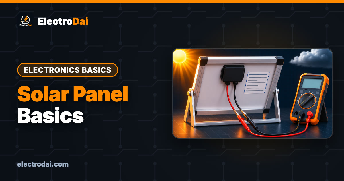
Solar power is a natural fit for projects in Nepal. A weather station on a roof, a sensor node in a field or a water tank monitor far from a socket can all run from a small panel and a battery. But many beginners connect a panel straight to a battery or an Arduino, see strange voltages, and end up with a swollen battery or a dead board.
This guide explains what the numbers on a solar panel label mean, how to measure a small panel with a multimeter, why you always need a charge controller between the panel and the battery, and how to log panel voltage with an Arduino. Everything here is low-voltage DC. Rooftop systems that connect to house wiring or an inverter are a job for a qualified electrician.
What you need
Scroll sideways to see all columns.
| Item | Qty | Notes |
|---|---|---|
| Small solar panel (1 W to 10 W) | 1 | "6 V" or "12 V" nominal hobby panel |
| Digital multimeter | 1 | DC volts and a 10 A current range |
| Arduino Uno (or compatible) | 1 | For the logging section |
| Resistors 39 kΩ and 10 kΩ | 1 each | Voltage divider for the Arduino |
| Capacitor 0.1 µF | 1 | Smooths the reading on A0 |
| Charge controller or solar charger module | 1 | Must match your battery chemistry |
| Fuse holder and fuse | 1 | Close to the battery |
| Jumper wires, breadboard | 1 set |
Reading the panel label
Turn the panel over. The sticker usually lists five numbers measured under Standard Test Conditions (STC): strong sunlight of 1000 W/m² and a cell temperature of 25 °C. Real sunlight in your courtyard will almost always give less.
Scroll sideways to see all columns.
| Label | Meaning | What it tells you |
|---|---|---|
| Pmax (W) | Maximum power at the best operating point | The size of the panel |
| Voc (V) | Open-circuit voltage, nothing connected | The highest voltage the panel can show; your controller must handle it |
| Vmp (V) | Voltage at maximum power | The working voltage under load |
| Isc (A) | Short-circuit current | The most current the panel can push |
| Imp (A) | Current at maximum power | The working current; Pmax ≈ Vmp × Imp |
This is why a "12 V" panel has a Voc of around 21 V and a Vmp of around 17 V to 18 V. The panel needs extra voltage to push charge into a 12 V lead-acid battery, which itself needs over 14 V to charge fully, and to make up for losses in heat, wiring and the controller. A "6 V" panel follows the same pattern at a smaller scale. Always read your own label instead of trusting the nominal number.
Two more points that surprise beginners:
- Cold raises Voc. On a cold, clear morning in the hills, the open-circuit voltage can go above the label value. Choose a controller rated with headroom above the panel's Voc.
- Shade kills current. Cells inside a panel are wired in series. Shading even one cell, with a leaf or the shadow of a pole, can drop the output far more than the shaded area suggests.
Measure a small panel: sun vs shade
You can see these numbers yourself with a multimeter. Do this with a small hobby panel only.
- Set the meter to DC volts (20 V or auto range).
- Put the panel in direct sun, facing the sun. Touch the red probe to panel + and the black probe to panel −. This is the open-circuit voltage. Write it down.
- Cover half the panel with a book, then the whole panel. Note how the voltage changes. Voltage often stays surprisingly high in light shade because it needs very little light to appear, which is exactly why voltage alone does not tell you how much power you are getting.
- To see current, move the red lead to the meter's 10 A socket, select the A range, and touch the probes across the panel for a second or two. On a small panel this reads roughly the short-circuit current, because the meter's current range is almost a short. Now shade the panel and watch the current fall sharply.
- Move the red lead back to the V socket when you finish. Leaving it in the 10 A socket is the most common way to blow a meter's fuse later.
Never try the current test on large rooftop panels or on any system already connected to batteries or inverters. If you are new to the meter, our guide on testing components with a multimeter covers the ranges and sockets.
Never connect a panel straight to a battery
It looks like free power, but a panel wired directly to a battery causes three problems:
- Overcharging. The panel keeps pushing current when the battery is full. Lead-acid batteries lose water and get damaged. Lithium cells can overheat, swell or catch fire.
- Wrong voltage. The battery's charging profile, its absorption and float voltages, depends on chemistry. A panel has no idea what chemistry it is connected to.
- Reverse current at night. Some panels let a small current flow back from the battery in the dark unless something blocks it.
A charge controller solves all three. It sits between the panel and the battery, limits the charging voltage, stops when the battery is full and prevents reverse flow.
Scroll sideways to see all columns.
| Controller type | How it works | Good for |
|---|---|---|
| PWM | Switches the panel on and off to hold the battery voltage | Small, cheap systems where Vmp is close to the battery voltage |
| MPPT | Converts voltage down while tracking the panel's best power point | Larger panels, or when panel voltage is much higher than the battery |
| Single-cell Li-ion solar charger IC | Charges one 3.7 V cell with a set current and cut-off | Tiny sensor nodes with one 18650 cell |
Rules for any setup:
- Match the chemistry. A lead-acid controller setting is wrong for lithium, and the other way round. Pick the setting or module made for your battery.
- Check the input limit. The panel's Voc, plus cold-weather headroom, must stay below the controller's maximum input voltage in its datasheet.
- Fuse near the battery. A battery can deliver a huge current into a short circuit. Put a fuse on the positive wire as close to the battery as practical.
- Connect in the controller's order. Most controllers want the battery connected first, then the panel. Follow its manual.
- Power the Arduino from the load or regulated output, not from the panel terminals.
Log panel voltage with an Arduino
A useful first experiment is to record how panel voltage changes through the day. The Uno's analog pin can only read 0 V to 5 V, so a voltage divider scales the panel voltage down.
With R1 = 39 kΩ and R2 = 10 kΩ:
V_pin = V_panel × R2 ÷ (R1 + R2) = V_panel × 10 ÷ 49
So 24.5 V at the panel gives 5 V at A0. That covers a "12 V" panel's Voc with some margin. If your panel's Voc could go above about 24 V, use a larger R1. The Ohm's law guide explains the maths.
Scroll sideways to see all columns.
| Connection | Goes to |
|---|---|
| Panel + | One end of R1 (39 kΩ) |
| R1 other end | Arduino A0, and one end of R2 (10 kΩ) |
| R2 other end | Arduino GND |
| 0.1 µF capacitor | Between A0 and GND |
| Panel − | Arduino GND |
// Solar panel voltage logger - not compiled yet
const int PANEL_PIN = A0;
const float R1 = 39000.0;   // top resistor (ohms)
const float R2 = 10000.0;   // bottom resistor (ohms)
const float VREF = 5.0;     // measure your board's 5V pin and put the real value here

void setup() {
  Serial.begin(9600);
  Serial.println("seconds,panel_volts");
}

void loop() {
  long total = 0;
  for (int i = 0; i < 16; i++) {      // average 16 readings
    total += analogRead(PANEL_PIN);
    delay(5);
  }
  float raw = total / 16.0;
  float vPin = raw * VREF / 1023.0;
  float vPanel = vPin * (R1 + R2) / R2;

  Serial.print(millis() / 1000);
  Serial.print(",");
  Serial.println(vPanel, 2);
  delay(10000);                       // one reading every 10 seconds
}
Copy the Serial Monitor output into a spreadsheet and draw a graph. Compare a clear day with a cloudy one. This open-circuit reading shows sunlight changes, not usable power. To see power you would also need to measure current under a load.
Troubleshooting
Scroll sideways to see all columns.
| Symptom | Likely cause | Fix |
|---|---|---|
| Meter shows 0 V in full sun | Broken lead or loose junction box | Check the wires at the back; test continuity |
| Voltage high but battery never charges | No current in shade, or controller in protection | Check current in full sun; read the controller's error LEDs |
| Arduino reads higher than the meter | VREF not equal to 5.0 V | Measure the 5V pin and update VREF |
| Arduino reading jumps around | No capacitor, long wires | Add the 0.1 µF capacitor, twist the leads |
| Meter dead in current mode | Fuse blown after an earlier test | Replace the meter fuse; always move the lead back to V |
| Battery warm or swelling | Wrong controller setting or no controller | Disconnect at once; use a controller matched to the chemistry |
FAQ
Can I power an Arduino directly from a solar panel?
Not reliably. Panel voltage swings with every cloud and goes to zero at night. Use the panel to charge a battery through a controller, then power the Arduino from the battery through a regulator.
Why does my 6 V panel show more than 7 V?
That is the open-circuit voltage with nothing connected. Under load it drops toward Vmp.
Is an MPPT controller always better?
For a 1 W to 5 W sensor node a simple charger is usually enough. MPPT gives a bigger benefit as panels get larger or when panel voltage is much higher than the battery.
Which way should the panel face in Nepal?
Nepal is in the northern hemisphere, so a fixed panel generally faces south and is tilted. For a moving panel, see our dual-axis solar tracker build.
Can I use this for my house's solar system?
No. This guide is for small, low-voltage learning projects. Home solar, inverters and anything connected to mains wiring must be installed by a qualified electrician.

Know Your Components: 18 Electronic Components, Their Types, Symbols and Units
Beginner guide to 18 electronic components: resistor, capacitor, diode, LED, transistor, MOSFET, regulator and more. Types, symbols, units and mistak…

How to Read a Datasheet in 5 Minutes (Beginner Guide)
Learn to read any electronics datasheet fast: absolute maximum ratings, operating conditions, electrical characteristics, pinout and typical applicat…

Arduino vs ESP32 vs Raspberry Pi: Which Board for Your Project?
Arduino Uno, ESP32 or Raspberry Pi? Compare logic voltage, Wi-Fi, OS, real-time control and power, then pick the right board for 10 common projects.