 Electro
ESP32 Pinout for Beginners: Safe Pins, Strapping Pins and ADC2 vs Wi-Fi
Which ESP32 GPIO pins are safe to use? Flash pins, strapping pins, input-only pins, 3.3 V logic and why ADC2 analog reads fail when Wi-Fi is on.
On this page
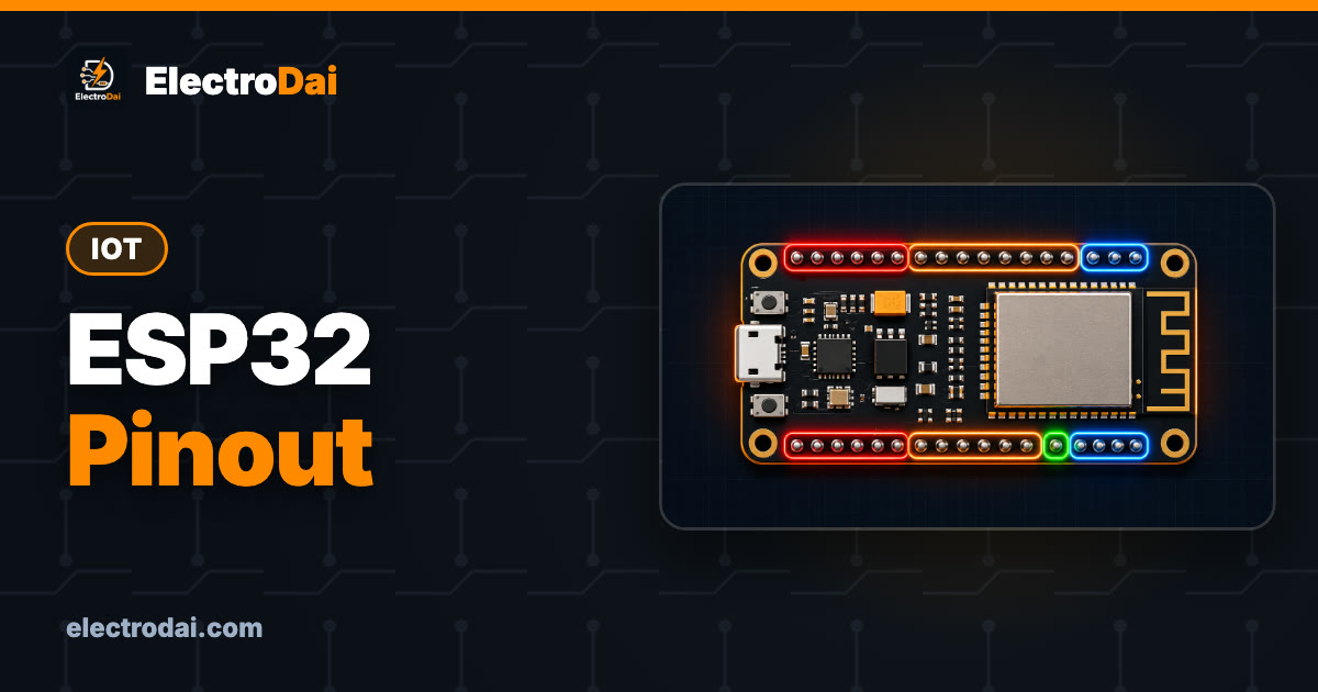
The ESP32 looks like it has pins to spare: around thirty GPIOs, Wi-Fi, Bluetooth, touch inputs and two DACs. Then you wire an LED to the "wrong" pin and the board refuses to upload, or your soil sensor reads zero the moment Wi-Fi connects.
Those problems are not bad luck. A few pins have special jobs, and once you know which ones, ESP32 projects become far less frustrating. This guide covers the original ESP32 (ESP32-WROOM-32 based DevKit boards, the most common kind in Nepal's hobby shops and college labs). Newer chips such as ESP32-S2, S3 and C3 have different pin maps, so check your board's pinout if you use one of those.
Rule zero: the ESP32 is a 3.3 V chip
An Arduino Uno works at 5 V. The ESP32's GPIO pins work at 3.3 V, and they are not designed to accept 5 V signals. Putting 5 V on a GPIO pin can damage it.
What this means in practice:
- An output HIGH is about 3.3 V, not 5 V.
- A 5 V sensor output (for example the HC-SR04 echo pin) needs a voltage divider or level shifter before it reaches the ESP32.
- 5 V I2C modules with on-board pull-ups to 5 V need a level shifter, or power the module from 3.3 V if its datasheet allows it.
- The "5V" or "VIN" pin on a DevKit is connected to USB power. It is a power pin, not a GPIO.
A quick voltage divider for a 5 V signal: 1 kΩ from the 5 V signal to the GPIO pin, and 2 kΩ from the GPIO pin to GND. That gives about 3.3 V at the pin. Our Ohm's law and resistor guide explains the maths.
Also keep the current small. A GPIO pin can light an LED through a resistor, but it cannot drive a motor, a relay coil or a buzzer that needs real current. Use a transistor or a driver module, and check the datasheet for the pin current limits.
Pins to never use: GPIO 6 to 11
On most ESP32 modules, GPIO 6, 7, 8, 9, 10 and 11 are connected to the on-board flash memory chip that holds your program. Using them for anything else usually crashes the board or stops uploads. Some DevKit boards do not even break these pins out, which is the easiest way to avoid them.
Strapping pins: careful at boot
When the ESP32 powers up or resets, it reads the state of a few pins to decide how to start: run your program, wait for a new upload, or select the flash voltage. These are the strapping pins: GPIO 0, 2, 5, 12 and 15.
You can still use them after boot, but anything connected to them must not force the wrong level during reset.
Scroll sideways to see all columns.
| Pin | What it does at boot | Beginner advice |
|---|---|---|
| GPIO 0 | LOW at boot = upload (download) mode. Connected to the BOOT button | Leave it for the BOOT button. Do not pull it LOW with a sensor |
| GPIO 2 | Must not be HIGH when entering upload mode. Often wired to the on-board LED | Fine for the LED; avoid circuits that pull it HIGH at reset |
| GPIO 5 | Strapping pin, normally HIGH at boot | Usually fine as an output; do not pull it LOW at reset |
| GPIO 12 | Sets the flash voltage. If it is HIGH at boot, many modules fail to start | Avoid. Never connect a pull-up or a module that holds it HIGH |
| GPIO 15 | Strapping pin; affects boot messages and timing | Usable with care; avoid pulling it LOW at reset |
If your board will not upload or boots in a loop, disconnect everything from the strapping pins first.
Input-only pins: GPIO 34 to 39
GPIO 34, 35, 36 and 39 (36 and 39 are often labelled VP and VN) can only read. They cannot be outputs, and they have no internal pull-up or pull-down resistors. If you connect a push button to one of them, add an external pull-up or pull-down resistor (10 kΩ is common).
They are excellent for analog sensors, because they are all on ADC1 (see below).
Serial pins: GPIO 1 and 3
GPIO 1 (TX0) and GPIO 3 (RX0) are connected to the USB-to-serial chip. They carry your uploads and Serial Monitor output. Using them for other things breaks uploads and printing. Leave them alone.
ADC2 stops working when Wi-Fi is on
The ESP32 has two analog-to-digital converters:
Scroll sideways to see all columns.
| ADC | GPIO pins |
|---|---|
| ADC1 | 32, 33, 34, 35, 36 (VP), 39 (VN) |
| ADC2 | 0, 2, 4, 12, 13, 14, 15, 25, 26, 27 |
The Wi-Fi driver uses ADC2 internally. When Wi-Fi is running, analogRead() on an ADC2 pin will fail or give useless values. This is the classic "my sensor reads zero after Wi-Fi connects" bug.
The fix is wiring, not code: move analog sensors to ADC1 pins (GPIO 32 to 39). If you need more than six analog inputs with Wi-Fi, use an external ADC module.
Two more ADC facts worth knowing:
- Readings run from 0 to 4095 (12-bit) by default, and with the default settings the usable range reaches roughly the 3.3 V supply.
- The ESP32 ADC is not perfectly linear, especially near 0 V and near the top. For better values, use
analogReadMilliVolts()(available in the ESP32 Arduino core) and avoid the extreme ends of the range.
Beginner-safe pin table
This is a practical summary for ESP32-WROOM-32 DevKit boards. Always confirm against your own board's printed labels.
Scroll sideways to see all columns.
| Use | Good pin choices | Notes |
|---|---|---|
| Digital outputs (LEDs, transistor bases, driver inputs) | 4, 13, 16, 17, 18, 19, 21, 22, 23, 25, 26, 27, 32, 33 | 16 and 17 may be unavailable on WROVER modules (used by PSRAM) |
| Digital inputs with internal pull-up | 4, 13, 14, 16 to 19, 21 to 23, 25 to 27, 32, 33 | GPIO 14 briefly outputs a signal at boot |
| Analog inputs with Wi-Fi on | 32, 33, 34, 35, 36, 39 | ADC1 only |
| Input-only (add external pull resistors) | 34, 35, 36, 39 | No pull-ups inside |
| I2C (default in Arduino) | SDA 21, SCL 22 | Can be moved to other pins in code |
| DAC (true analog out) | 25, 26 | 8-bit |
| Avoid | 6 to 11 (flash), 1 and 3 (USB serial), 12 (boot voltage) | |
| Use with care | 0, 2, 5, 15 (strapping) | Nothing that forces a level at reset |
Test it: ADC1 reading with Wi-Fi on
Connect a 10 kΩ potentiometer: one end to 3.3 V, the other end to GND, and the middle (wiper) to GPIO 34. Never connect the pot end to 5 V.
Scroll sideways to see all columns.
| Potentiometer pin | ESP32 pin |
|---|---|
| Outer pin 1 | 3V3 |
| Wiper (middle) | GPIO 34 |
| Outer pin 2 | GND |
// ADC1 read with Wi-Fi connected - not compiled yet
#include <WiFi.h>

const char* WIFI_SSID = "YourWiFi";
const char* WIFI_PASS = "YourPassword";
const int POT_PIN = 34;   // ADC1 pin: works with Wi-Fi on

void setup() {
  Serial.begin(115200);
  WiFi.begin(WIFI_SSID, WIFI_PASS);
  Serial.print("Connecting");
  while (WiFi.status() != WL_CONNECTED) {
    delay(500);
    Serial.print(".");
  }
  Serial.println();
  Serial.print("Connected, IP: ");
  Serial.println(WiFi.localIP());
}

void loop() {
  int raw = analogRead(POT_PIN);            // 0 to 4095
  int mv  = analogReadMilliVolts(POT_PIN);  // calibrated millivolts
  Serial.printf("raw=%d  mV=%d\n", raw, mv);
  delay(500);
}
Turn the knob and the values should change smoothly while Wi-Fi stays connected. Now move the wiper wire to an ADC2 pin such as GPIO 26 and change POT_PIN. With Wi-Fi on, the readings will no longer behave. That is ADC2 in action.
Troubleshooting
Scroll sideways to see all columns.
| Symptom | Likely cause | Fix |
|---|---|---|
| Upload fails with "waiting for download" or timeout | Something on GPIO 0, 2, 12 or 15 is forcing a level | Disconnect strapping pins; hold BOOT while upload starts |
| Board boot-loops after wiring a module | GPIO 12 held HIGH, or a flash pin (6 to 11) used | Move the wire to a safe pin |
| Analog reads 0 or random once Wi-Fi connects | Sensor on an ADC2 pin | Move it to GPIO 32 to 39 |
| Button on GPIO 34 to 39 reads random values | No internal pull-up on input-only pins | Add a 10 kΩ external pull-up or pull-down |
| Serial Monitor shows nothing | GPIO 1 or 3 used in your circuit, or wrong baud rate | Free those pins; match the baud rate in code |
| Pin stopped working after a 5 V sensor | 5 V on a 3.3 V pin may have damaged it | Use a divider or level shifter; try another pin |
FAQ
Is the ESP32 5 V tolerant?
No. Treat every GPIO as 3.3 V only and use a divider or level shifter for 5 V signals.
Can I power the ESP32 DevKit from 5 V?
Yes, through the USB port or the 5V/VIN pin, which feeds the board's 3.3 V regulator. That is different from putting 5 V on a GPIO pin.
Why does my board have pins labelled D23 or G23?
Different manufacturers label pins differently. The number is the GPIO number used in code: write 23, not D23.
Does this apply to ESP32-S3 or ESP32-C3?
No. Those chips have different pin maps, strapping pins and ADC rules. Look up the pinout for your exact chip and board.
What should I build next?
Try the ESP32 web server that controls an LED from your phone, then the ESP32 Blynk dashboard.

TinyML on ESP32 with Edge Impulse: Your First On-Device Model
Train a gesture recognition model with Edge Impulse and run it on an ESP32 with an MPU6050. Data collection, training, int8 deployment and testing.

ESP32-CAM Getting Started: Upload, Flash LED and Motion Photo
Upload code to the ESP32-CAM with a USB-serial adapter, fix brownout and Connecting errors, use the GPIO4 flash LED, and take a PIR motion photo.

Landslide Tilt Warning Prototype with MPU6050 and LoRa (Learning Build)
Build a learning prototype that detects tilt with an MPU6050 on an ESP32 and sends alerts over LoRa to a gateway. Wiring, code, testing and limits.