 Electro
Know Your Components: 18 Electronic Components, Their Types, Symbols and Units
Beginner guide to 18 electronic components: resistor, capacitor, diode, LED, transistor, MOSFET, regulator and more. Types, symbols, units and mistakes.
On this page
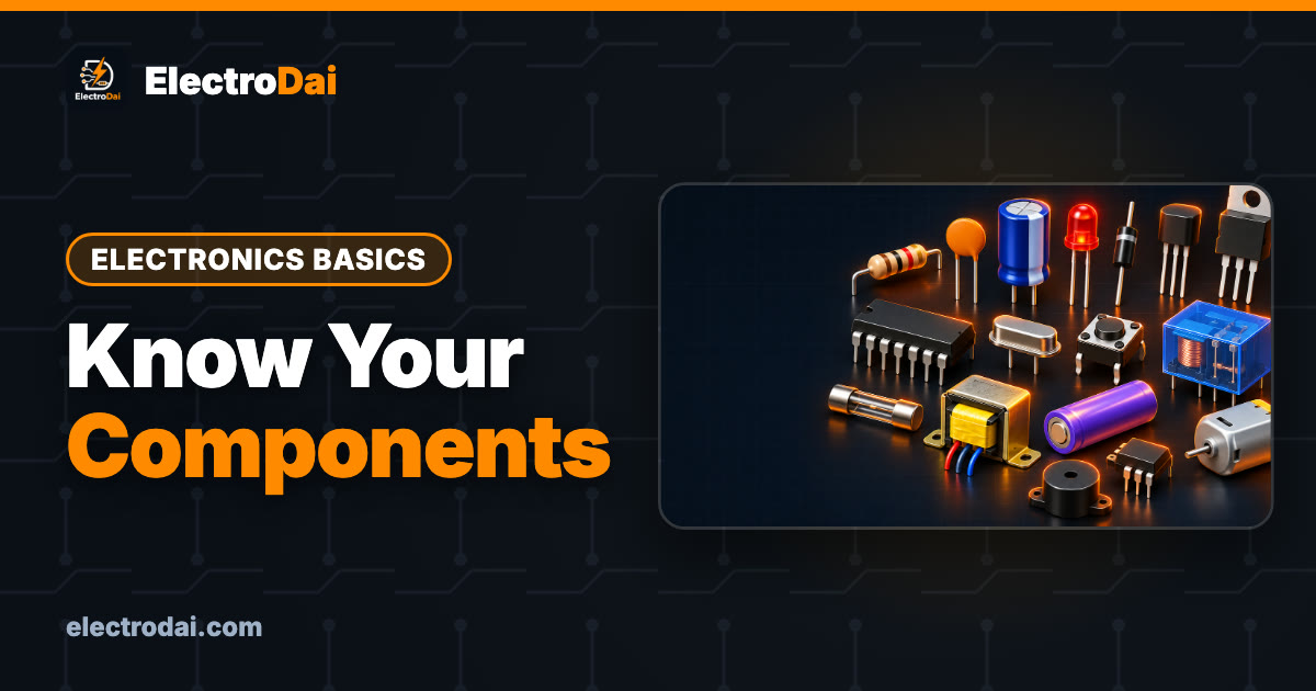
You open a starter kit or pull apart an old board and see dozens of little parts: striped cylinders, blue cans, black chips, silver crystals, blue relay cubes. Before you can build anything confidently, you need to recognise each part, know its circuit symbol, read its value, and avoid the classic mistake that kills it.
This is the ElectroDai Know Your Components guide. It covers the 18 components every beginner, +2 science student and BE or BSc CSIT student meets in Arduino and electronics projects. For each one you get the main types, the schematic symbol, the unit and how to read the value, and one beginner mistake to avoid. Bookmark it and come back whenever a part confuses you.
Quick units table
Scroll sideways to see all columns.
| # | Component | Main unit / rating | Example marking or value |
|---|---|---|---|
| 1 | Resistor | ohm (Ω, kΩ, MΩ) | brown-black-red-gold = 1 kΩ ±5 % |
| 2 | Capacitor | farad (pF, nF, µF) | 104 = 100 nF = 0.1 µF |
| 3 | Inductor | henry (µH, mH, H) | 100 (SMD) = 10 µH |
| 4 | Diode | max current (A), max reverse voltage (V) | 1N4007 = 1 A, 1000 V |
| 5 | LED | forward voltage (V), current (mA) | red ≈ 2 V at 10–20 mA |
| 6 | Transistor (BJT) | gain (hFE), max current (mA) | BC547: 100 mA, 45 V |
| 7 | MOSFET | max V (VDS), max A (ID), RDS(on) | IRLZ44N: 55 V, logic-level gate |
| 8 | Voltage regulator | output voltage (V), current (A) | 7805 = 5 V out |
| 9 | IC | supply voltage, pin count | NE555, LM358, 74HC595 |
| 10 | Crystal / resonator | hertz (Hz, kHz, MHz) | 16.000 MHz |
| 11 | Switch | contact rating (V, A) | 12 V DC 50 mA (tactile) |
| 12 | Relay | coil voltage (V), contact rating (A) | coil 5 V DC, contacts 10 A |
| 13 | Fuse | current (A), speed (F/T), voltage | T1A 250V |
| 14 | Transformer | voltage (V), power (VA) | 230 V to 12 V, 12 VA |
| 15 | Battery | voltage (V), capacity (mAh) | 18650: 3.7 V nominal |
| 16 | Buzzer / speaker | impedance (Ω), frequency (Hz) | speaker 8 Ω |
| 17 | Motor | voltage (V), speed (RPM) | SG90 servo: about 4.8–6 V |
| 18 | Photodiode / optocoupler | LED current (mA), CTR (%) | PC817 optocoupler |
The prefixes are the same everywhere: k = × 1000, M = × 1,000,000, m = ÷ 1000, µ = ÷ 1,000,000, n = ÷ 1,000,000,000, p = ÷ 1,000,000,000,000.
1. Resistor
What it does: limits current and divides voltage.
Types: fixed resistors (carbon film, usually beige; metal film, usually blue), the potentiometer (an adjustable resistor with three legs, the middle one is the wiper), the LDR (light-dependent resistor, resistance falls in bright light) and the thermistor (NTC type: resistance falls as temperature rises).
Symbol: a zigzag line (US style) or a plain rectangle (IEC style, common in Nepal and India textbooks). A potentiometer adds an arrow pointing at the body (the wiper). An LDR adds two arrows pointing in (light falling on it). A thermistor has a diagonal line through it with a short flat end.
Unit and how to read it: ohm (Ω). 1 kΩ = 1000 Ω, 1 MΩ = 1,000,000 Ω. On a 4-band resistor: band 1 and band 2 are digits, band 3 is the multiplier (number of zeros), band 4 is tolerance (gold ±5 %, silver ±10 %). Brown-black-red-gold = 1, 0, × 100 = 1 kΩ ±5 %. Red-red-brown = 22 × 10 = 220 Ω. Pots are printed like "B10K" (10 kΩ; on most Asian-made pots, B = linear, A = logarithmic). A "10K NTC" thermistor is 10 kΩ at 25 °C.
Beginner mistake: reading the colour bands from the wrong end. The gold or silver tolerance band goes on the right. Also check the power rating: a common small resistor is 1/4 W.
2. Capacitor
What it does: stores charge for a short time; smooths supplies, removes noise, blocks DC and sets timing.
Types: ceramic disc and MLCC (no polarity), aluminium electrolytic (polarized), tantalum (polarized), film/box (no polarity), supercapacitor (very large values at low voltage, usually polarized) and variable/trimmer capacitors.
Symbol: two straight parallel lines = non-polarized. One straight and one curved plate = polarized (the curved plate is negative). IEC style shows one hollow plate with a + sign. An arrow through it = variable.
Unit and how to read it: farad (F). 1 µF = 1000 nF = 1,000,000 pF. Electrolytics print the value directly (470µF 25V). Small ceramics use a 3-digit code in picofarads: first two digits = value, third = number of zeros. 104 = 10 × 10⁴ pF = 100,000 pF = 100 nF = 0.1 µF. 103 = 10 nF, 222 = 2.2 nF, and a two-digit "47" = 47 pF. Tolerance letters: J ±5 %, K ±10 %, M ±20 %.
Beginner mistake: the stripe trap. On an aluminium electrolytic, the stripe marks negative and the longer leg is positive. On a tantalum, the stripe or bar marks positive. A reversed electrolytic can bulge or burst; a reversed tantalum can short and burn. Also pick a voltage rating above your circuit voltage (a common rule of thumb is 1.5 to 2 times).
3. Inductor
What it does: stores energy in a magnetic field and resists sudden changes in current. Used in buck converters, filters and radio circuits.
Types: air-core coil, coil on a ferrite rod or ring (toroid), small axial "resistor-like" inductors with colour bands, SMD power inductors, and the ferrite choke/bead clipped on cables to stop noise.
Symbol: a row of loops or humps. Two straight lines beside the loops mean a magnetic core (iron or ferrite).
Unit and how to read it: henry (H). 1 mH = 1000 µH. Small inductors are coded in microhenries: "100" = 10 × 10⁰ = 10 µH, "101" = 100 µH, "4R7" = 4.7 µH (R is the decimal point). The current rating matters as much as the inductance.
Beginner mistake: forgetting that coils (inductors, relay coils, motors) make a voltage spike when switched off. Switching a coil with a transistor needs a flyback diode across it. And in a buck converter, an inductor with too low a current rating overheats.
4. Diode
What it does: lets current flow one way only.
Types: rectifier diodes (1N4007: 1 A, up to 1000 V reverse), small signal diodes (1N4148), Zener diodes (used in reverse to hold a fixed voltage, such as 5.1 V), and Schottky diodes (1N5819, lower forward drop, fast).
Symbol: a triangle pointing at a bar. The bar is the cathode. Zener: the bar has bent ends (like a Z). Schottky: the bar has S-shaped hooks.
Unit and how to read it: diodes are rated by maximum forward current (A) and maximum reverse voltage (V). A silicon diode drops about 0.6–0.7 V when conducting (a 1N4007 can show close to 1 V at its full current); a Schottky drops less, roughly 0.2–0.45 V. The band on the body marks the cathode, the same as the bar in the symbol.
Beginner mistake: using a Zener without a series resistor. Without it, the Zener takes too much current and burns.
5. LED
What it does: a diode that gives light.
Types: normal 3 mm/5 mm LEDs, RGB LEDs (four legs, common anode or common cathode; the longest leg is the common one), and IR LEDs (invisible infrared, used in remotes and sensors; many phone cameras can show the IR glow).
Symbol: a diode symbol with two arrows pointing out (light leaving).
Unit and how to read it: forward voltage (V) and current (mA). Roughly, red is about 1.8–2.2 V, blue and white about 3.0–3.3 V, IR about 1.2–1.5 V. 10–20 mA is typical for a 5 mm LED; always check your LED's datasheet. Long leg = anode (+); the flat edge on the rim marks the cathode (−).
Beginner mistake: connecting an LED with no series resistor. Use R = (supply − LED voltage) ÷ current. From 5 V for a red LED at about 14 mA: (5 − 2) ÷ 0.014 ≈ 214 Ω, so use 220 Ω. See our Ohm's law and LED resistor guide.
6. Transistor (BJT)
What it does: a small base current controls a larger collector current. Used as a switch or amplifier.
Types: NPN (BC547, 2N2222) and PNP (BC557, 2N2907). Small ones come in the three-leg TO-92 package; power types come in TO-220.
Symbol: a bar (base) with two slanted lines; the one with the arrow is the emitter. NPN: the arrow points out ("Not Pointing iN"). PNP: the arrow points in.
Unit and how to read it: gain (hFE or β): collector current ≈ gain × base current. Maximum collector current (BC547: 100 mA) and voltage (BC547: 45 V). The part number printed on the flat face tells you everything; look up its datasheet for the pinout.
Beginner mistake: assuming every TO-92 transistor has the same pinout. A BC547 is usually C-B-E (flat face toward you, legs down), but a 2N2222 in TO-92 is usually E-B-C. Always check, and always use a base resistor. Our transistor as a switch guide explains the calculation.
7. MOSFET
What it does: a voltage on the gate switches a big current between drain and source, with almost no gate current. Ideal for motors, LED strips and solenoids.
Types: N-channel (used on the low side, between load and ground; e.g. IRLZ44N, IRF540N) and P-channel (high side; e.g. IRF9540N). Pins: Gate, Drain, Source (on many TO-220 MOSFETs: G-D-S from left, text facing you; check the datasheet).
Symbol: the gate is a line separated from the channel by a gap (it is insulated). The arrow on the body points in for N-channel and out for P-channel.
Unit and how to read it: VDS (max drain-source voltage), ID (max current), RDS(on) (on-resistance in Ω or mΩ, lower = cooler) and VGS(th) (the gate voltage where it starts to turn on, not where it is fully on).
Beginner mistake: driving a standard MOSFET like the IRF540N from a 5 V or 3.3 V Arduino/ESP32 pin. Its RDS(on) is specified at 10 V gate drive, so at 5 V it may only half turn on and get hot. Choose a logic-level MOSFET (such as IRLZ44N for 5 V) and add a 10 kΩ gate pull-down resistor to ground.
8. Voltage regulator
What it does: gives a steady output voltage from a higher input.
Types: 7805 (fixed 5 V linear), AMS1117-3.3 (3.3 V low-dropout linear, found on many ESP32 and Arduino boards), LM317 (adjustable linear, about 1.25 V up to 37 V), and buck converter modules (switching, e.g. LM2596 boards, much more efficient).
Symbol: usually drawn as a box with IN, GND (or ADJ) and OUT pins.
Unit and how to read it: the part number tells the output voltage (7805 = 5 V, 7812 = 12 V, AMS1117-3.3 = 3.3 V). A 7805 needs about 2 V of headroom, so give it at least about 7 V in. LM317: Vout ≈ 1.25 × (1 + R2 ÷ R1). A linear regulator burns the extra voltage as heat: P = (Vin − Vout) × I.
Beginner mistake: assuming all TO-220 regulators share one pinout. A 7805 is IN-GND-OUT, but an LM317 is ADJ-OUT-IN. On a buck module, set the output with the trimmer and a multimeter before connecting your board. See our power guide.
9. IC (integrated circuit)
What it does: a whole circuit in one chip.
Types for beginners: the 555 timer (8 pins, makes delays and blinking), the op-amp (e.g. LM358, two op-amps in 8 pins) and the shift register (74HC595, 16 pins, gives 8 extra outputs from 3 Arduino pins).
Symbol: a rectangle with numbered pins (555, 74HC595). An op-amp is a triangle with two inputs: + (non-inverting) and − (inverting).
Unit and how to read it: the printed part number (NE555, LM358, 74HC595) and the datasheet. Check the supply range: an NE555 runs on about 4.5–16 V, a 74HC595 on about 2–6 V. A 555 astable runs at about f ≈ 1.44 ÷ ((R1 + 2 × R2) × C); see our 555 LED flasher.
Beginner mistake: putting the chip in the wrong way round. Pin 1 is next to the notch or dot. Looking from the top, pins count anticlockwise.
10. Crystal and resonator
What it does: gives a microcontroller a precise clock.
Types: quartz crystal (often the silver HC-49 can, two legs; very accurate) and ceramic resonator (three legs, the middle one is ground, load capacitors built in; less accurate but cheaper). Arduino Uno boards run at 16 MHz from a crystal or a ceramic resonator, depending on the board.
Symbol: a thin rectangle between two plates (like a capacitor with a box inside). A resonator symbol often adds the ground leg.
Unit and how to read it: hertz (Hz). 1 MHz = 1,000,000 Hz. The can is printed with the frequency, such as "16.000" (MHz).
Beginner mistake: building a standalone ATmega328P with a crystal but no load capacitors. A crystal needs two small capacitors from each leg to ground (22 pF is the common value for 16 MHz; check the crystal's datasheet). Keep the crystal close to the chip.
11. Switch
What it does: opens or closes a circuit by hand.
Types: tactile push button (momentary, 4 legs), slide switch, toggle switch and rocker switch (latching). Terms: SPST (one contact), SPDT (changeover), NO (normally open), NC (normally closed).
Symbol: SPST = a line hinged open, like a gate. Push button = two contacts with a bridging bar and a small plunger (T) on top.
Unit and how to read it: the contact rating, such as "12 V DC 50 mA" for small tactile buttons, or a higher current and voltage printed on toggle and rocker switches. Never exceed it.
Beginner mistake: on a 4-leg tactile button, the legs are connected in pairs inside. Place it across the breadboard's centre gap and use diagonal legs, or it may be "always pressed". Also, an Arduino input needs a pull-up or pull-down resistor (or INPUT_PULLUP), or it floats.
12. Relay
What it does: a small coil current moves a switch that can control a separate, bigger load.
Types: bare relays (e.g. SRD-05VDC-SL-C) and 5 V relay modules with a transistor, a flyback diode and an LED already on the board.
Symbol: a coil (rectangle) and a switch, joined by a dashed line to show they move together.
Unit and how to read it: coil voltage (05VDC = 5 V DC coil) and contact rating printed on the top (for example 10 A at 250 V AC / 30 V DC on many blue relays). Terminals: COM (common), NO (normally open, connects to COM when the relay is on) and NC (normally closed, connected when off). Many modules are active LOW: the relay turns on when the input pin is LOW.
Beginner mistake: driving a bare relay coil straight from an Arduino pin (too much current, plus a voltage spike). Use a module or a transistor plus a flyback diode. Mains wiring is for a qualified electrician; practise with a low-voltage lamp or motor. More in our relay module guide.
13. Fuse
What it does: breaks the circuit when the current is too high, to prevent fire and damage.
Types: glass cartridge fuses (fast-blow "F" and slow-blow "T"), blade fuses (vehicles) and the polyfuse (PTC, resettable; it heats and limits current, then recovers when it cools). An Arduino Uno has a 500 mA polyfuse protecting your USB port.
Symbol: a rectangle with a line running through it (IEC). Some US diagrams draw an S-shaped curve.
Unit and how to read it: current in amps plus speed and voltage: T1A 250V = slow-blow (time-lag), 1 A, rated for 250 V. F500mA = fast-blow, 0.5 A.
Beginner mistake: replacing a blown fuse with a higher rating, or with a piece of wire. Find out why it blew first. (This includes the fuse inside your multimeter.)
14. Transformer
What it does: changes an AC voltage up or down using two coils on an iron core.
Types for beginners: step-down transformers, for example 230 V AC to 12 V AC (Nepal's mains is 230 V, 50 Hz), and small PCB transformers. Switching chargers use tiny high-frequency transformers inside.
Symbol: two coils facing each other, with two straight lines between them for the iron core.
Unit and how to read it: primary and secondary voltage (V) and power in VA (volt-amperes). 12 V at 1 A = 12 VA. Voltage ratio = turns ratio: Vp ÷ Vs = Np ÷ Ns.
Beginner mistake: expecting DC from the secondary. A transformer gives AC; you need a rectifier and a smoothing capacitor for DC (and the unloaded voltage is often higher than the label). The primary side is mains: leave that wiring to a qualified electrician, and use a ready-made adapter for your projects.
15. Battery
What it does: stores energy and supplies DC.
Types: AA (alkaline 1.5 V, rechargeable NiMH 1.2 V), the 9 V PP3 battery, 18650 lithium-ion cells (3.7 V nominal, 4.2 V full) and coin cells like the CR2032 (3 V).
Symbol: a long thin line (positive) and a short thick line (negative). Several pairs in a row mean a multi-cell battery.
Unit and how to read it: voltage (V) and capacity in mAh. In an ideal case, 2000 mAh could supply 200 mA for about 10 hours; real life gives less.
Beginner mistake: powering motors or a robot from a 9 V battery. It has small capacity and cannot give much current. Also be suspicious of 18650 cells claiming huge numbers like "9900 mAh"; those are usually fake. Charge lithium cells only with a proper charger. See our 18650 battery safety guide.
16. Buzzer and speaker
What it does: makes sound.
Types: active buzzer (has a built-in oscillator; beeps when you apply DC; often sealed underneath), passive buzzer (no oscillator; you must send a frequency, e.g. with Arduino tone(); often an open PCB underneath) and the speaker (paper cone and magnet).
Symbol: a speaker is a small rectangle with a flared cone. Buzzers are often drawn as a bell-like half-circle shape; styles vary, so read the label.
Unit and how to read it: speakers are rated by impedance (often 8 Ω) and power (W). Sound frequency is in Hz; people hear roughly 20 Hz to 20 kHz. Small buzzers are loudest around a few kHz. Active buzzers often mark the + leg.
Beginner mistake: connecting an 8 Ω speaker straight to an Arduino pin. 5 V ÷ 8 Ω would ask for about 0.6 A, far above what a pin can give. Use a series resistor (for example 100 Ω) for a quiet test, or a small amplifier module. And calling tone() on an active buzzer won't play notes properly.
17. Motor
What it does: turns electricity into motion.
Types: DC motors (including the yellow TT gear motor, about 3–6 V), servo motors (SG90: about 4.8–6 V, turns to an angle 0–180°; wires: brown = GND, red = V+, orange = signal) and stepper motors (28BYJ-48 with a ULN2003 board, or NEMA 17 with a driver like A4988).
Symbol: a circle with the letter M.
Unit and how to read it: rated voltage (V), speed in RPM (revolutions per minute), and current (A), especially the stall current, which is much higher than the running current.
Beginner mistake: powering a motor from an Arduino pin or from the Arduino's 5 V pin. Motors need a driver (transistor, MOSFET, L298N or a servo/stepper driver) and their own supply, with the grounds connected. Otherwise the Arduino resets or gets damaged. See our L298N motor driver guide.
18. Photodiode and optocoupler
What it does: a photodiode turns light into a small current. An optocoupler passes a signal using light, so two circuits stay electrically isolated.
Types: photodiodes (often in IR receivers and light sensors), phototransistors, and optocouplers like the PC817 (an IR LED and a phototransistor inside one 4-pin chip).
Symbol: a photodiode is a diode with two arrows pointing in (the opposite of an LED). An optocoupler shows an LED and a phototransistor side by side in a box, with arrows from the LED to the transistor.
Unit and how to read it: for an optocoupler, the input LED current (mA) and the CTR (current transfer ratio, in %): output current ÷ input current. A photodiode's current is tiny (often µA).
Beginner mistake: connecting the optocoupler's input LED without a resistor, exactly like an ordinary LED. And remember that a photodiode is normally used reverse-biased (cathode to the more positive side) in a light sensor.
How to keep learning
- Get a small parts box and label every compartment with the value and the unit.
- Measure parts with a multimeter: our multimeter testing guide covers resistors, diodes, capacitors and LEDs.
- For anything new, read the datasheet's absolute maximum ratings and pinout first. Our datasheet guide shows how in five minutes.
FAQ
Which components should a beginner buy first?
A resistor kit, LEDs, 0.1 µF ceramic and 100 µF electrolytic capacitors, 1N4007 diodes, BC547 transistors, push buttons, a buzzer and a breadboard cover most first projects.
Are circuit symbols the same everywhere?
Mostly. Resistors (zigzag vs rectangle) and polarized capacitors (curved plate vs hollow plate) have two common styles: the US style and the IEC style used in many Nepali and Indian textbooks. Both mean the same thing.
Why do some parts have a polarity and others don't?
Polarized parts (diodes, LEDs, electrolytic and tantalum capacitors, batteries, many buzzers) are built so current or voltage must go one way. Resistors, ceramic capacitors, inductors and most switches work either way round.
What is the difference between mA and mAh?
mA is current (how fast charge flows right now). mAh is battery capacity (how long that current can last). A 1000 mAh battery could ideally give 100 mA for 10 hours.
Is a stripe always negative?
No. On an aluminium electrolytic capacitor the stripe is negative. On a diode the band marks the cathode. On a tantalum capacitor the stripe or bar is positive. Always read the + and − signs or the datasheet.
Watch the video
The ElectroDai long video "Every Electronic Component Explained: Types, Symbols and Units (18 Components)" walks through all 18 parts with drawn symbols on screen, and there is a 30–45 second Short for each component. Find them on YouTube @electrodai.

How to Read a Datasheet in 5 Minutes (Beginner Guide)
Learn to read any electronics datasheet fast: absolute maximum ratings, operating conditions, electrical characteristics, pinout and typical applicat…

Arduino vs ESP32 vs Raspberry Pi: Which Board for Your Project?
Arduino Uno, ESP32 or Raspberry Pi? Compare logic voltage, Wi-Fi, OS, real-time control and power, then pick the right board for 10 common projects.

Solar Panel Basics for Arduino Projects: Voc, Vmp and Charge Controllers
Read a solar panel label (Voc, Vmp, Isc, Imp), measure a small panel with a multimeter, and charge a battery safely with a charge controller.